Compression fittings look simple: a nut, a ferrule, and a tube. Yet a small installation error can cause leakage, vibration damage, or costly rework. Their reliability depends on details often hidden from view: clean, square tube ends; compatible materials; correct insertion depth; and controlled tightening. The right method can vary by fitting design, manufacturer, and service conditions.
Technical references such as Swagelok’s Tube Fitter’s Manual and ASME B31.3 provide useful context for sound fitting practice and process-piping quality. They also reinforce an important point: installation instructions are not interchangeable. A turn count or assembly method intended for one product may not suit another. Check the fitting manufacturer’s current instructions, use the specified tools, and inspect the finished joint under appropriate conditions.
This guide explains how to install compression fittings with practical steps, from preparing the tube to checking the completed connection. A clear bench, a deburring tool, and careful measurement matter more than force. Small details matter. The source material supplied for this request contains no verifiable industry market-data report or named compression-fitting expert quotation. Rather than invent a statistic or attribute an unsupported statement, this introduction relies on identifiable technical references; add a sourced expert quotation before publication if one is required.
How to Install Compression Fittings?
Identify the Fitting Components and Check Compatibility
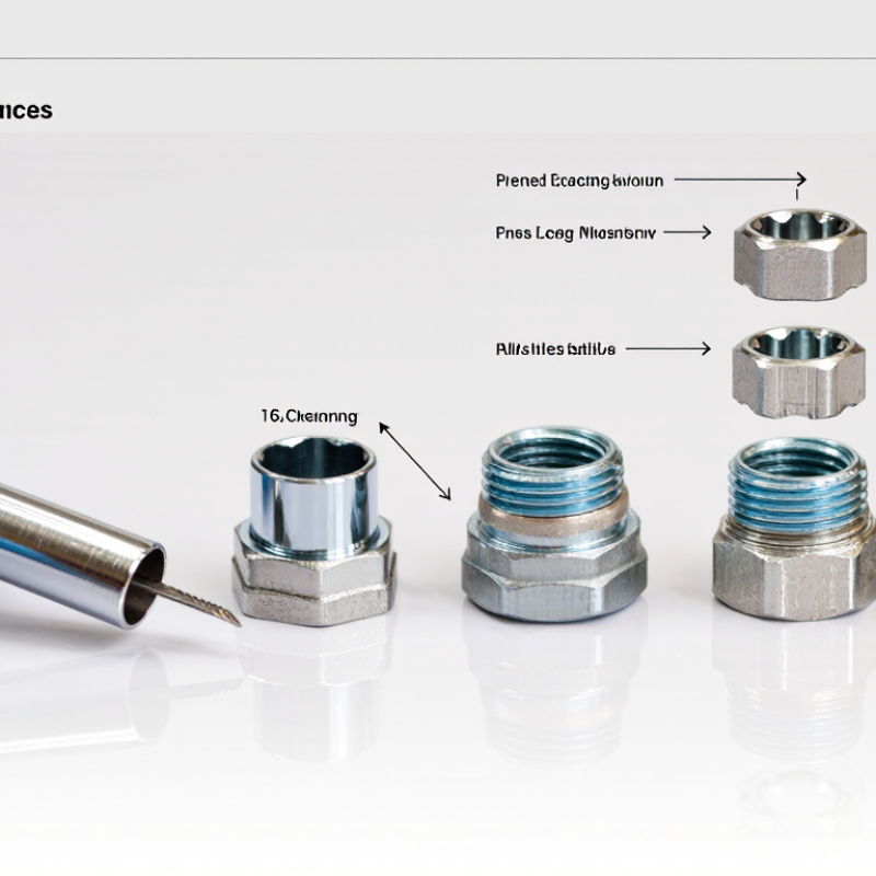
Before assembly, lay out the fitting body, compression nut, and ferrule on a clean bench. Some designs use two ferrules, so check the fitting’s instructions rather than assuming every set is alike. Small parts matter. Look for cracks, flattened edges, corrosion, or a ferrule that has already been compressed.
Match the fitting to the tubing’s exact outside diameter, material, and wall thickness. A tube that looks close may still leak or fail to seat. Confirm that the fitting materials suit the fluid, operating temperature, and pressure; these limits vary by design. Check that the threads align and the tube end is square, smooth, and free of burrs. Do not guess. Mixing nuts or ferrules from different fitting styles can prevent a reliable seal, even when the parts appear to fit. I have found that a quick size check is easy to skip when a job feels familiar; it is worth slowing down here. Use the specified assembly method, and replace damaged or previously compressed components when the instructions call for it.
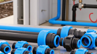
Identify the fitting body, nut, and ferrule(s). Before assembly, verify the fitting is designed for the tube’s outside diameter, material, and application, and confirm the connection thread type.
Tube outside diameter conversions: 1 inch equals 25.4 millimeters. Match the actual tube OD to the fitting specification; these sizes are not interchangeable.
Before assembly, make the line safe to handle: shut off the supply, release trapped pressure, and confirm the tube is empty. Check that the tube’s outside diameter, material, and wall thickness match the fitting’s requirements. A mismatch may look minor, but it can prevent a dependable seal. Measure the section carefully and leave enough straight tube for the fitting to grip.
Cut the tube square with a suitable cutter, not with a crushing motion that leaves it oval. Inspect the end under good light. Remove inside and outside burrs, then wipe away chips, oil, and grit with a clean, lint-free cloth. Keep it clean. A tiny shaving can interfere with seating. Check the fitting body, nut, and ferrule for damage, dirt, or deformation; replace questionable parts rather than trying to smooth them by hand. Slide the nut and ferrule onto the tube in the specified order and orientation. The details vary by fitting design, so verify them against the maker’s instructions. Push the tube gently into the fitting until it bottoms out, then mark its position if useful. I have found that a quick visual check here is easy to skip—and worth repeating before tightening.
Cut the tube square, then remove burrs from both the inside and outside edges. A slanted cut can prevent the compression ring from seating evenly. Wipe away dust and check that the tube is clean, round, and free of deep scratches. Mark the recommended insertion depth with a pencil or marker. This gives you a visible check later. Small detail, big effect.
Slide the compression nut onto the tube, then position the ring as specified for that fitting. Ring shape and orientation can vary, so do not assume every design is identical. Guide the tube fully into the fitting body until it reaches its stop, keeping it straight as you work. Pause here. Check that your depth mark is near the fitting entrance and that the ring has not shifted out of place. This step can feel fiddly, and a crooked start is easy to miss. If the tube catches or the ring tilts, stop and inspect the parts rather than forcing them. Once aligned, hold the tube steady while tightening the nut according to the fitting instructions. Over-tightening may deform the ring or damage the tube. After assembly, check for leaks using the method recommended for the system.
After inserting clean, square-cut tubing, bring the compression nut finger-tight. Hold the fitting body steady with one wrench and turn the nut with another. This prevents the tube from twisting. Follow the fitting maker’s specified number of turns or torque; there is no reliable universal value. Too little tightening may leave a leak path, while excessive force can deform the ferrule or damage the tube. Small changes matter.
The U.S. Department of Energy’s Improving Compressed Air System Performance: A Sourcebook for Industry estimates that leaks can waste 20–30% of compressor output in poorly maintained systems. That figure covers system leaks broadly, not compression joints alone, but it shows why careful assembly and leak checks matter. After tightening, pressurize the line gradually and inspect the joint using an approved leak-detection method. If leakage persists, depressurize before adjusting or replacing components. Retightening a live connection is not worth the risk.
Tips: Mark the nut and fitting body before tightening; the marks make rotation easier to track. Check the tube for scratches and keep it fully seated. I’d still verify the product instructions twice—turn counts vary, and that detail is easy to overlook.
After assembly, inspect the joint before restoring pressure. The tube should enter the fitting straight and sit fully against its internal stop. Check that the ferrule is evenly seated, with no visible gap or tilted edge. The nut should be snug, not forced. A wrench can make a fitting feel secure while hiding a crooked tube. If the tubing is scratched, oval, or cut at an angle, take it apart and prepare a clean end. Small details matter here. Look closely.
Open the supply slowly and watch the connection as pressure returns. Wipe the nut and fitting dry, then hold a clean tissue around the joint for several seconds. Even a tiny bead can show on paper before it becomes a drip. Check again after a few minutes, and once more after the line has been used. No moisture is a good sign, but it is not a guarantee. If a leak appears, shut off and depressurize the line before adjusting the nut. Tighten only in small increments and follow the fitting instructions; excessive force may deform the ferrule or tubing. If it still leaks, disassemble and inspect rather than repeatedly tightening.

Cepex is the brand for the fluid handling market belonging to the Fluidra group. One of the leading european manufacturer of valves and fittings in thermoplastic materials.
Dedicated to the swimming pool, irrigation and industrial markets, we distribute our products worldwide with the Fluidra commercial network and presence in 46 countries with 136 sales branches.