Choosing an actuated valve is not just a matter of matching pipe size. It means matching the valve, actuator, controls, and process conditions. The IEA’s Tracking Industry 2023 report estimates that industry accounts for about 37% of global energy use. That figure does not mean a valve alone can deliver major energy savings. It does show why reliable flow control matters across energy-intensive plants.
Start with the job the valve must do. Is it isolating a line, throttling flow, or controlling pressure? Then check the medium, temperature, pressure, flow range, and expected cycle frequency. A valve that works well with clean water may behave differently with steam or a slurry. Actuator torque must also cover the valve’s operating load, including the pressure difference across it. Small details matter. A tight enclosure, corrosive washdown, or loss of power can change which actuator and fail position are suitable.
Compare electric, pneumatic, and hydraulic options against the site’s utilities, control signals, response time, and maintenance capacity. Check mounting and interface compatibility, including ISO 5211 where applicable, and confirm the complete assembly’s ratings with manufacturer documentation. The uncomfortable truth: no actuator type is best for every service. Even a neat datasheet can leave questions about operating conditions or failure behavior. A careful choice of actuated valves therefore starts with the process, then verifies the full valve-and-actuator package against real operating needs.
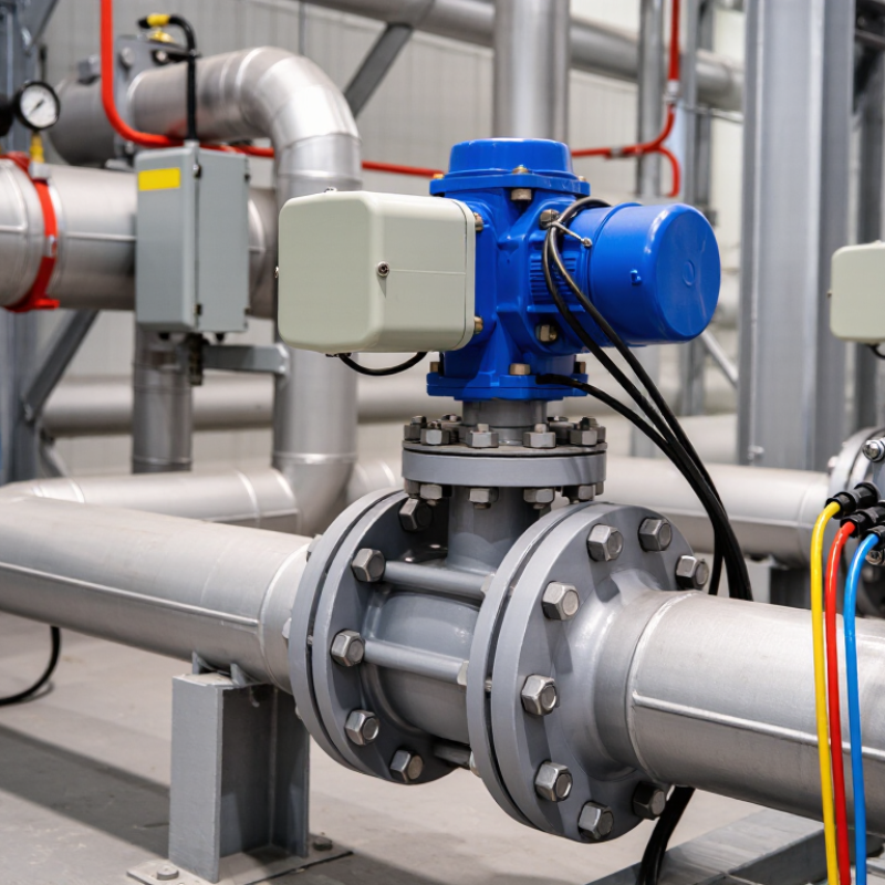
For liquid service, estimate the required valve capacity with Cv = Q√(SG/ΔP), using Q in gpm and ΔP in psi. SG is the liquid’s specific gravity relative to water. ΔP means the pressure drop across the valve at the intended flow—not the system’s total pressure. For example, 40 gpm of water with a 4 psi valve drop gives a Cv of 20. Check that the pressure values reflect normal operating conditions. A calculation based only on peak flow can lead to a valve that performs poorly during everyday operation.
Tips: Confirm units before calculating. Small unit errors matter. Use the liquid’s actual specific gravity, especially for dense fluids. This equation is for liquid sizing; gas and steam require different methods. Cv is a starting point, not a complete selection.
Compare the calculated Cv with the valve’s published capacity, then consider its usable operating range. A valve that is oversized may open only slightly, making flow control less stable. Also verify materials, temperature limits, shutoff needs, and the actuator’s torque at the maximum expected pressure differential. The actuator must move the valve reliably under real conditions. I would still review the result against the process data; assumptions about pressure drop can be wrong, and that is easy to miss.
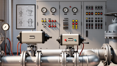
Choosing an actuated valve starts with the process, not the actuator alone. Identify the fluid, operating temperature, pressure drop, flow range, and required shutoff performance. A globe valve may suit demanding throttling, while a rotary valve can offer compact installation and high capacity. Neither choice guarantees tight shutoff. Small details matter.
IEC 60534-4 provides test procedures and leakage classes for control valves. Class IV is a common metal-seat specification; Class V permits less leakage under defined test conditions, while Class VI is often selected for very low leakage with soft seats. These are not interchangeable labels for “leak-free.” State the required class, test medium, pressure differential, and acceptance criteria, then check the valve’s published test data. A soft seat may meet a tighter class, but temperature, fluid compatibility, and wear can limit its suitability. On site, debris or seat damage may change performance. That part is easy to underestimate. Match the leakage requirement to the consequence of leakage, and confirm the actuator can provide the needed seating force at the worst-case differential pressure. A neat specification can still miss real operating conditions.
Choose the valve style for the required flow control, then specify a seat-leakage class appropriate to the shutoff requirement.
Reading the chart: IEC 60534-4 Classes II, III, and IV limit leakage to 0.5%, 0.1%, and 0.01% of rated valve capacity, respectively. Classes V and VI use different acceptance criteria and are not directly comparable on this scale. Globe valves are commonly selected for modulating control; rotary ball or butterfly valves may suit quarter-turn applications. Confirm the valve, actuator, and leakage class against the process conditions and applicable test requirements.
Choosing an actuated valve starts with matching actuator output torque to the valve’s breakaway torque. Breakaway torque is the force needed to move a closed valve from its seat, and it can be higher than the torque needed later in the stroke. Compare figures at the same operating conditions. A number without context can mislead.
Check the actuator’s available torque at the actual air pressure or electrical supply, not just its maximum rating. Then compare it with the valve’s highest expected torque, including changes in pressure, temperature, fluid, and seat condition. Leave a suitable margin for variation, but avoid oversizing without checking the valve stem’s allowable torque. Too much force can damage components. I have seen calculations look neat on paper, yet overlook low air pressure or a sticky valve after downtime. That deserves a second look.
Pneumatic actuators are a practical choice when plant air is already available. Typical supply pressure is 3–8 bar, but check pressure at the actuator during operation, not only at the compressor. Confirm air quality, valve torque, stroke time, and required fail position. Small detail, big consequence. A spring-return unit may provide a defined response on air loss, but it also needs enough torque to move the valve under actual process conditions.
The U.S. Department of Energy’s Improving Compressed Air System Performance sourcebook reports that compressed air uses about 10% of U.S. industrial electricity, and can reach 30% at some facilities. That energy cost makes leaks and oversizing worth checking.
Electric actuation suits sites that need repeatable positioning, control signals, or diagnostics without air tubing. Check duty cycle, available power, enclosure protection, and what happens during a power failure. Hydraulic actuation can deliver high force in a compact package, making it useful for demanding loads; however, pumps, fluid lines, and leak checks add equipment and maintenance.
Get specific. Compare actuator output with the valve’s required torque across the full stroke, including pressure and temperature effects. A selection based only on nominal torque can look fine on paper and still struggle in service. I would also verify the real utility conditions with maintenance staff; drawings do not always show the whole picture.
Choosing an actuated valve starts with its pressure-temperature rating, not the actuator size. ASME B16.34-2020 provides rating tables linked to material groups and operating temperatures. A Class 300 valve is not automatically rated for 300 psi at every temperature. Check the exact body material, pressure class, end connection, and design temperature against the standard. Then compare that rating with normal pressure and credible surges in the line. Small detail, big consequence. A rating copied from a cold-water duty may not suit a hot process.
Mounting needs the same care. ISO 5211:2017 specifies interface dimensions and drive components for part-turn actuators, helping verify that the actuator flange and valve stem fit together. Match the flange designation, bolt pattern, and stem shape; then confirm the actuator can deliver the valve’s required breakaway torque at the worst operating condition. Torque demand can rise with pressure, temperature, deposits, or aging seals. Standards define the interface, but they do not replace application checks. I still recheck drawings against the actual valve, because a nominally matching flange can hide a stem mismatch. Sources: ASME B16.34-2020; ISO 5211:2017.

Cepex is the brand for the fluid handling market belonging to the Fluidra group. One of the leading european manufacturer of valves and fittings in thermoplastic materials.
Dedicated to the swimming pool, irrigation and industrial markets, we distribute our products worldwide with the Fluidra commercial network and presence in 46 countries with 136 sales branches.