MPO Cable assemblies connect many optical fibers through compact, multi-fiber connectors. They are common in data centers and other high-density networks, where space and rapid installation matter. That sounds simple. The choices are not.
Common configurations include trunk cables, breakout harnesses, conversion assemblies, and short patch cords. A trunk cable links MPO ports across a longer route, often between a distribution panel and equipment. A breakout harness divides an MPO connection into individual connectors, such as LC connectors, for devices that need separate fiber links. Conversion assemblies join different connector formats or fiber counts. Patch cords handle shorter connections within a rack or cabinet.
Cable type is only part of the decision. Fiber count, single-mode or multimode fiber, connector gender, and polarity also affect compatibility. Polarity describes how transmit and receive paths align between connected equipment. Type A, Type B, and Type C arrangements use different fiber mappings, so they are not interchangeable by default. Still, the naming can feel less clear than it should. A label alone may not reveal whether an assembly suits a specific link.
Before choosing, check equipment documentation, port requirements, and the complete link design. For example, a breakout cable may fit a switch port physically but fail to match the required fiber mapping. Verify connector type, fiber specification, length, and polarity with the supplier or network designer. Small details matter. This guide compares the main MPO Cable types and explains where each configuration is typically useful, so readers can assess options with fewer assumptions.
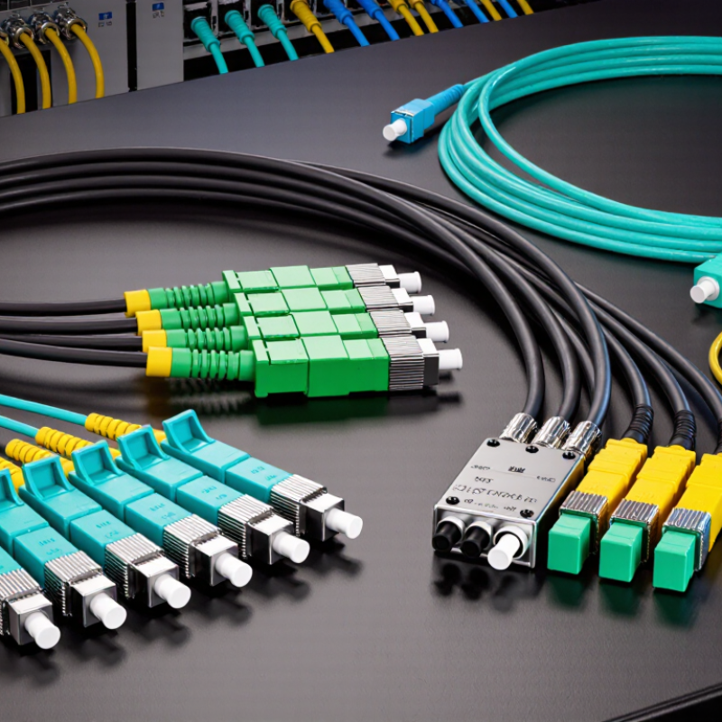
MPO cable fiber counts describe the number of optical fibers arranged in the connector, but they do not tell the whole story. An 8-fiber format can support parallel transmit and receive paths in compatible systems. It uses fewer fibers than a 12-fiber assembly. Check the transceiver specification before choosing.
Twelve-fiber cables are widely used in trunks and structured cabling. Some links use only eight positions, leaving four unused; that can be intentional. Sixteen-fiber formats provide a denser array for equipment designed around that layout. They are not automatically interchangeable with 12-fiber cables. The connector may look similar, yet its fiber arrangement can differ.
Twenty-four-fiber cables often serve as backbone trunks between panels, where multiple channels need to fit in limited space. Thirty-two-fiber versions pack even more connections into a compact route, but careful polarity planning matters. Small details count. Confirm fiber count, polarity, connector gender, and optical loss against the equipment documents. A practical lesson: counting fibers is a useful starting point, not a complete selection method. Cable labels can be unclear, and a mismatch may leave fibers dark even when the connector fits.

An eight-fiber MPO trunk carries the four transmit and four receive lanes used by 40GBASE-SR4. Each lane runs at 10 Gb/s, delivering an aggregate 40 Gb/s over multimode fiber. IEEE 802.3ba-2010 specifies a maximum link reach of 100 meters on OM3 and 150 meters on OM4. These figures assume compliant cabling and channel conditions; they are not a guarantee for every installed link.
Eight active fibers. No spare pair.
The connector can have more positions than the cable uses: MPO-12 assemblies commonly leave four positions unused for this application. Polarity must route each transmit lane to the corresponding receive lane at the far end. TIA-568.3-E provides cabling guidance, while IEEE’s 40 GbE specifications define the transmission requirements.
In practice, technicians should verify fiber type, polarity, connector cleanliness, and end-to-end loss before deployment. Dust is easy to overlook. So is a reversed polarity. I would not assume an existing MPO trunk is compatible from its connector shape alone; inspect its fiber count and polarity method, then test the installed channel.
MPO harness cables connect a high-density MPO trunk to individual LC duplex ports. This makes them useful when switches or panels use MPO cabling, but connected equipment accepts two-fiber LC interfaces. A 12-fiber MPO can serve up to six duplex ports when the fiber mapping matches the system. The harness separates the array into short LC legs, making each connection easier to route and identify.
Check the fiber count and polarity before ordering. A connector that fits may still map transmit and receive fibers incorrectly. Confirm the cable’s fiber type, MPO key orientation, and LC connector polish against the installed link. For example, six labeled LC pairs are easier to trace than loose, unmarked legs inside a crowded rack. Small details matter.
Allow enough slack for service, but avoid tight bends near the breakout point. Excessive pulling can stress the fan-out, even when the main trunk looks secure. Inspect and clean connectors before mating them, then test each duplex path for continuity and loss. A tidy harness is helpful, but appearance alone proves little. Port labels and test records can prevent avoidable troubleshooting later. Mapping assumptions are easy to miss, so verify them at both ends.
MPO polarity describes how fibers connect from one cable end to the other. It matters because transmitter and receiver positions must align across the link. In a typical 12-fiber Type A cord, fiber 1 connects to fiber 1, and the sequence stays straight. Type B reverses the sequence: fiber 1 connects to fiber 12. Type C flips adjacent pairs, so fibers 1 and 2 swap, as do 3 and 4. Small changes, but they affect the whole path.
Connector key positions can help identify a layout, but they should not be the only check. Their appearance depends on how you view each connector. Before installation, confirm the cable’s polarity label and test end-to-end mapping with a suitable polarity tester. Then check that the cassette or transceiver arrangement matches the cord. A tidy label can still be wrong. I would verify it rather than trust it blindly, especially when several patch cords look identical. One missed reversal may leave a link dark, or create confusing troubleshooting results.
OM4 is a 50/125-micrometer multimode fiber commonly used for short-reach data-center links. With compatible optics, it supports 100GBASE-SR4 over distances of up to 100 meters. The link operates at 850 nm and sends data across four lanes in each direction. That means eight fibers carry traffic. A 12-fiber MPO connector is often used, with the remaining positions unused for this link. Check the equipment and cabling layout rather than assuming every MPO cable is wired the same way.
The 100-meter figure is a maximum, not a guarantee for every installation. Connector loss, patch panels, cable quality, and transceiver compatibility all affect the usable channel. Clean end faces matter. Small details count. In practical planning, verify polarity and confirm that the complete channel meets the required loss budget. A cable may be labeled OM4 yet still be unsuitable if its connectors are poorly aligned or its routing adds too much loss. It is easy to focus on fiber mode alone; I would treat that as an incomplete check, especially when several MPO connections sit between the switches.
| Fiber type | Fiber mode | Typical MPO fiber count | Example 100G application | Typical maximum reach | Practical notes |
|---|---|---|---|---|---|
| OM3 | Multimode | 8 active fibers; commonly an MPO-12 connector with positions left unused | 100GBASE-SR4 | Up to 70 m | A common short-reach option; reach depends on the standards-compliant channel and transceivers. |
| OM4 | Multimode | 8 active fibers; commonly an MPO-12 connector with positions left unused | 100GBASE-SR4 | Up to 100 m | A widely used multimode choice for 100G SR4 links in data centers. |
| OM5 | Wideband multimode | 8 active fibers for SR4; commonly an MPO-12 connector | 100GBASE-SR4; also designed for wideband multimode applications such as SWDM | Up to 100 m for SR4 when supported by the transceiver specification | Its wideband capability can support multiple wavelengths; confirm that the optics use the intended technology. |
| OS2 | Single-mode | 12 fibers are commonly used for 100GBASE-PSM4 | 100GBASE-PSM4 with compatible MPO interfaces | Up to 500 m for PSM4 | Single-mode links require matching single-mode optics; reach varies by application and channel design. |
| OM1 / OM2 | Multimode | Varies by cable assembly | Not typically specified for 100GBASE-SR4 | No standard SR4 reach listed | Use the fiber grade and transceiver combination specified for the target Ethernet application. |
Reach figures are application limits, not guarantees for every installation. Actual link performance depends on the transceivers, channel loss, connector condition, polarity, and cabling design.

Cepex is the brand for the fluid handling market belonging to the Fluidra group. One of the leading european manufacturer of valves and fittings in thermoplastic materials.
Dedicated to the swimming pool, irrigation and industrial markets, we distribute our products worldwide with the Fluidra commercial network and presence in 46 countries with 136 sales branches.