What Is OPGW in Transmission Lines and How Does It Work?
FLUID HANDLING EXPERTS

Blog, all our news

What Is OPGW in Transmission Lines and How Does It Work?

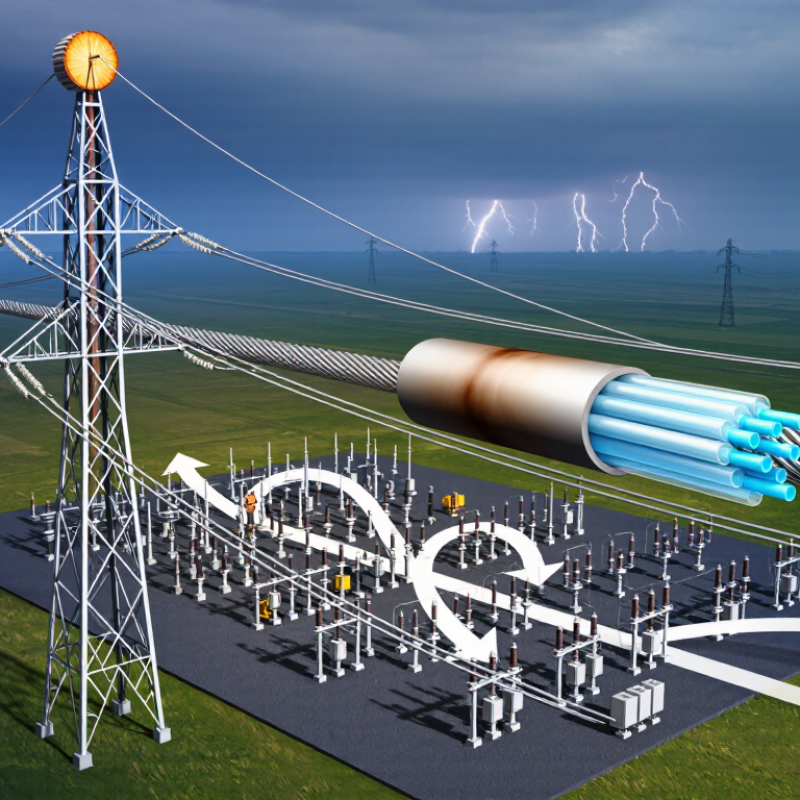
Opgw In Transmission Line technology combines two essential functions in one overhead cable: lightning protection and high-speed communication. Its metallic strands shield phase conductors, while internal optical fibers carry data between substations. A typical installation runs along the tower peak, where a sudden flash may leave small burn marks on the outer wires, yet the fiber core continues supporting protection signals, voice services, and grid monitoring.

The International Energy Agency’s Electricity Grids and Secure Energy Transitions report estimates that about 80 million kilometres of grids must be added or replaced globally by 2040. This pressure makes reliable communication infrastructure increasingly important. IEEE 1138 also provides detailed guidance for OPGW design, testing, and application. These standards help engineers evaluate short-circuit current, tensile strength, sag, vibration, and fibre attenuation before installation.

As fibre-optic specialist David W. Smith explains, “OPGW succeeds when electrical protection and communication reliability are designed as one system.” That principle sounds simple, but field conditions are less forgiving. Ice loading, corrosion, tower geometry, and poor joint closures can weaken an otherwise excellent design. Engineers must inspect actual spans, not trust catalogue values alone.

This article explains what Opgw In Transmission Line means, how the cable works, and why utilities select it for modern transmission networks. Some projects still underestimate maintenance access. That deserves closer review.
What Is OPGW in Transmission Lines and How Does It Work?

OPGW Structure: 24–48 Optical Fibers Integrated into a Shield Wire

What Is OPGW in Transmission Lines and How Does It Work?

OPGW combines a shield wire with optical communication fibers. Its central tube commonly contains 24–48 optical fibers, protected by aluminum or steel strands. The outer strands intercept lightning above high-voltage conductors. Inside, fibers carry protection signals, voice, and high-speed monitoring data. No separate communication cable is required.

The design supports modern grid expansion. The International Energy Agency’s Electricity Grids and Secure Energy Transitions report estimates that over 80 million kilometers of grids must be added or refurbished by 2040. OPGW can help utilities improve communication across these long routes. IEEE 1138-2021 also emphasizes mechanical, electrical, and fiber-performance requirements for overhead ground wires. In field work, installers must control pulling tension and bending radius. Small installation errors can create hidden attenuation. That risk is easy to underestimate.

Tips: Check fiber count, short-circuit rating, sag, and tower loading together. Fiber capacity alone is not enough. Leave spare fibers when future monitoring is likely. Inspect joints carefully after installation. Field conditions rarely match the drawing perfectly.

What Is OPGW in Transmission Lines and How Does It Work? - OPGW Structure: 24–48 Optical Fibers Integrated into a Shield Wire

Data Dimension Typical or Representative Data Role in Transmission Lines
Product name Optical Ground Wire (OPGW) Combines overhead lightning-shielding and fiber-optic communication functions in one conductor.
Typical installation position Mounted at the top of a transmission tower or substation gantry The elevated position allows the wire to intercept lightning strokes before they reach phase conductors.
Optical-fiber capacity 24–48 optical fibers are common in many transmission-line designs Provides communication channels for protection, control, voice, data, and remote monitoring systems.
Fiber type Usually single-mode glass fiber, commonly specified for 1310 nm and 1550 nm transmission windows Supports long-distance, low-loss optical communication along the transmission corridor.
Fiber unit protection Stainless-steel tube or aluminum-covered stainless-steel tube surrounding the fibers Protects fibers from moisture, mechanical stress, temperature changes, and installation tension.
Outer conductive layers Aluminum alloy wires, aluminum-clad steel wires, or a combination of conductive and strength wires Provides electrical conductivity, mechanical strength, corrosion resistance, and protection for the optical unit.
Mechanical function Designed to withstand everyday tension, wind, ice, vibration, and installation loads Maintains required sag and clearance while carrying the optical unit across tower spans.
Lightning protection function Acts as a grounded overhead shield wire Receives lightning current and routes it through tower grounding systems toward earth.
Communication principle Electrical signals are converted into light pulses and transmitted through the glass fibers Enables high-speed, electrically isolated data transmission without using the metallic shield-wire path for the signal.
Electrical conductivity Specified by the required DC resistance and short-circuit current rating Determines how effectively the OPGW carries lightning and fault currents without excessive heating.
Outer diameter Commonly about 8–20 mm, depending on fiber count, strength, current rating, and span requirements Affects wind loading, ice loading, fittings, sag, and compatibility with existing tower hardware.
Unit mass Often approximately 300–1,000 kg/km, depending on construction and load requirements Influences tower loading, stringing equipment, transportation, and installation planning.
Operating temperature range Commonly specified around −40°C to +70°C; the exact range depends on the design Ensures stable mechanical and optical performance under seasonal and fault-current temperature conditions.
Short-circuit current rating Project-specific; commonly rated from several kiloamperes to more than 30 kA for a defined duration Indicates the short-duration fault current that the metallic OPGW components can withstand thermally.
Fiber attenuation Typically not greater than about 0.35 dB/km at 1310 nm and 0.22 dB/km at 1550 nm for standard single-mode fiber Lower attenuation permits longer communication distances and fewer optical regeneration points.
Common reference standards IEC 60794-4, IEC 61089, IEEE 1138, and applicable national utility specifications Standards define requirements for optical performance, mechanical strength, electrical properties, testing, and installation.
Main applications Transmission-line protection, telecommunication, SCADA, substation automation, and grid monitoring Uses the existing overhead line route to provide reliable utility communications without installing a separate fiber cable.
Note: OPGW values are design-dependent. Final dimensions, fiber count, optical loss, tensile strength, sag, and short-circuit rating should be selected according to the transmission-line span, environmental conditions, fault level, and applicable project standards.

OPGW Fault Protection: IEEE 1138 Grounding and Short-Circuit Performance

OPGW carries optical fibers inside a metallic overhead ground wire. It shields transmission lines from lightning and provides a communications path for protection systems. During a line-to-ground fault, fault current can enter the OPGW, tower steel, and buried grounding system. The current divides according to conductor impedance, tower footing resistance, and nearby shield-wire connections.

IEEE Std 1138 evaluates OPGW mechanical strength, electrical continuity, and short-circuit performance through controlled tests. Its approach focuses on temperature rise, fiber protection, and residual tensile strength after fault exposure.

Thermal duty follows the I²t principle: higher current or longer duration creates greater heating. A 40 kA fault lasting 0.5 seconds produces 800 megajoules per ohm of current-time stress. That figure is a calculation, not a universal OPGW rating.

CIGRE technical guidance also treats tower footing resistance as a major factor in lightning and fault behavior. Lower resistance usually improves current dissipation, but it cannot compensate for weak bonding or damaged fittings.

Field inspections should check clamps, splice closures, corrosion, and fiber attenuation after severe faults. Small defects matter.

One practical limitation remains: laboratory results may not represent unequal current sharing across a long line. Engineers should verify local fault levels, clearing times, and grounding measurements before selecting a wire size. Mistakes often begin with assuming every tower carries the same current.

OPGW Communication: ITU-T G.652.D Fibers with 0.35 dB/km Loss at 1310 nm

In overhead transmission lines, OPGW combines a ground wire with optical communication fibers. It sits above phase conductors and helps shield the line from lightning. Inside its metallic layers, protected fibers carry voice, protection, and operational data between substations. This dual role saves tower space, but installation demands careful tension control. Excessive pulling force can damage fibers before any alarm appears.

For reliable communication, many OPGW designs use ITU-T G.652.D single-mode fibers. These fibers support transmission near 1310 nm, where a specified loss of 0.35 dB/km can preserve useful power over long routes. The actual link budget also includes splice loss, connector loss, bends, and aging. A cable length alone never proves performance. Technicians should test each fiber with an optical time-domain reflectometer and a calibrated light source.

At a substation, optical transceivers convert electrical data into light pulses. The pulses travel through the fiber core while the aluminum or steel structure handles mechanical and grounding duties. In my field experience, clean splices often matter more than impressive headline specifications. A small caveat matters. The 0.35 dB/km figure is not automatically guaranteed for every cable, wavelength, or temperature. Engineers should verify the product datasheet, route length, reserve margin, and acceptance-test results before energizing the communication circuit.

OPGW Installation on 110–1,000 kV Lines: Sag, Tension, and Clearances

OPGW combines an overhead ground wire with optical fibers, so installation must satisfy both electrical and mechanical demands. On 110–1,000 kV lines, the voltage level affects clearance requirements, but it does not determine sag alone. Span length, terrain, conductor arrangement, wind, ice, temperature, and tower geometry matter more.

Before stringing, engineers calculate initial and final sag-tension conditions. They include conductor creep, everyday temperature, maximum wind, and possible ice loading. During installation, controlled tension keeps the OPGW clear of tower steel and the ground. Stringing blocks should match the cable diameter and maintain the approved bending radius. Small mistakes here can damage fibers without visible marks.

Clearance checks must cover phase conductors, tower members, roads, buildings, and crossings. The lowest sag point deserves careful attention. It may shift with temperature. Grounding and bonding at every tower also support reliable fault-current performance and communications continuity. Field crews should record actual tension, weather, reel length, and clamp locations. A neat spreadsheet can still mislead when site conditions change. That is worth challenging.

Designers should verify calculations against applicable utility specifications and recognized transmission-line standards. A qualified engineer must approve final settings for each span, especially near steep terrain or long crossings. OPGW installation is not simply “pull and clamp.” It is a controlled balance between sag, tension, clearance, and fiber protection.

OPGW Testing and Maintenance: IEC 60794 Optical and Mechanical Requirements

What Is OPGW in Transmission Lines and How Does It Work?

OPGW combines an overhead earth wire with optical fibres for communication. It shields transmission lines from lightning and carries protection, control, and data signals. Its metallic layers handle mechanical stress, while the sealed optical unit protects fibres from moisture and temperature changes.

OPGW testing should follow the applicable IEC 60794 requirements and the project specification.

Optical checks commonly include fibre continuity, attenuation, and optical return performance. Mechanical verification may include tensile strength, bending, crushing, torsion, and vibration resistance. These tests help confirm that installation has not damaged the cable.

During field work, technicians should inspect suspension points, joints, grounding connections, and unusual strand movement.

Small aluminium marks can reveal serious rubbing over time.

A clean test result is not the whole story. Records may miss weather exposure or tension changes. That gap deserves attention.

Tips:

Test fibres before installation, after stringing, and after joint closure. Compare results with baseline measurements, not only pass or fail limits.

Use calibrated instruments and record temperature, cable length, test wavelength, and test location.

During maintenance, photograph damaged fittings and measure optical loss consistently.

Never treat visual inspection as optional. A cable can appear sound while hidden fibre stress is increasing.

Also review the current IEC edition and contract requirements, because project limits may differ from general guidance.

Copyright 2025 Fluidra S.A. | Created by BCM Marketing Agencia Privacy Policy Legal note | Cookie policy |

Technical cookies are strictly necessary for our website to work and you can navigate through it. These types of cookies are those that, for example, allow us to identify you, give you access to certain restricted parts of the page if necessary, or remember different options or services already selected by you, such as your privacy preferences. Therefore, they are activated by default, your authorization not being necessary in this regard. Through the configuration of your browser, you can block or alert the presence of this type of cookies, although such blocking will affect the proper functioning of the different functionalities of our website.


The analysis cookies allow us to study the navigation of the users of our website in general (for example, which sections of the page are the most visited, which services are used most and if they work correctly, etc.). From the statistical information on navigation on our website, we can improve both the operation of the page itself and the different services it offers. Therefore, these cookies do not have an advertising purpose, but only serve to make our website work better, adapting to our users in general. By activating them you will contribute to this continuous improvement. You can enable or disable these cookies by checking the corresponding box, being disabled by default.


Functionality cookies allow us to remember your preferences, to personalize certain characteristics and general options of our website, every time you access it (for example, the language in which the information is presented to you, the sections marked as favorites, your browser type, etc.) Therefore, this type of cookies does not have an advertising purpose, but by activating them you will improve the functionality of the website (for example, adapting to your type of browser) and the customization of it based on your preferences (for example, by presenting the information in the language that you have chosen in previous occasions), which will contribute to the ease, usability and comfort of our page during your navigation. You can enable or disable these cookies by checking the corresponding box, being disabled by default.


Advertising cookies allow us to manage the advertising spaces included in our website based on criteria such as the content shown or the frequency in which the ads are displayed. For example, if you have been shown the same ad several times on our website, and you have not shown a personal interest by clicking on it, it will not appear again. In summary, by activating this type of cookies, the advertising shown on our website will be more useful and diverse, and less repetitive. You can enable or disable these cookies by checking the corresponding box, being disabled by default.


Behavioral advertising cookies allow us to obtain information based on the observation of your browsing habits and behaviors on the web, in order to show you advertising content that best suits your personal tastes and interests. To understand it in a very simple way, we will give you a fictitious example: if your last searches on the web were related to suspense literature, we would show you advertising about suspense books. Therefore, activating this type of cookies, the advertising that we show you on our website will not be generic, but will be oriented to your searches, tastes and interests, therefore adjusting exclusively to you. You can enable or disable these cookies by checking the corresponding box, being disabled by default.
To understand it in a very simple way, we will give you a fictitious example: if your last searches on the web were related to suspense literature, we would show you advertising about suspense books. Therefore, activating this type of cookies, the advertising that we show you on our website will not be generic, but will be oriented to your searches, tastes and interests, therefore adjusting exclusively to you. You can enable or disable these cookies by checking the corresponding box, being disabled by default.

SAVE

We use our own and third-party cookies to ensure the proper functioning of the website and to analyse our services, improve your experience on our website and show you advertisements related to your interests according to profiling based on your browsing habits (e.g. websites visited). You can accept all cookies by clicking "ACCEPT" or set or reject them by clicking here. If you would like to know more about the use of cookies, please see our COOKIE POLICY.


ACCEPT ALL
Reject no essentials