Choosing plastic ball valves is not a simple matter of matching pipe diameter.
The correct choice depends on fluid chemistry, temperature, pressure, flow rate, and installation conditions.
Plastics Europe reported 413.8 million tonnes of global plastics production in 2023.
That scale reflects plastics’ importance across water treatment, chemical processing, and industrial piping.
Grand View Research’s 2024 industrial valves analysis also identifies water and wastewater systems as major demand sectors.
Yet broad market growth does not guarantee the right valve for every process.
Asahi/America technical expert Tom Deakins states, “Material compatibility must be considered before pressure rating.”
That principle deserves attention.
A valve may fit perfectly but fail early when exposed to solvents, heat, or abrasive media.
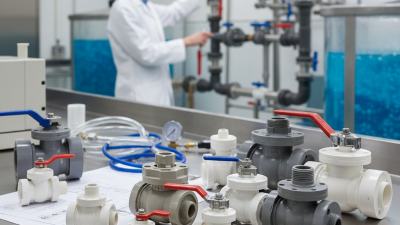
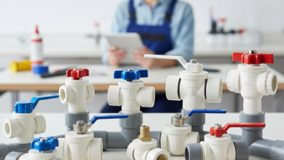
PVC, CPVC, PP, and PVDF each behave differently under real operating stresses.
A practical selection process should examine the valve body, seats, seals, connection method, and actuation requirements.
For example, EPDM seals may suit water service, while chemical duties can require PTFE or FKM.
Pressure ratings must also be checked at the actual operating temperature, not room temperature.
Small details matter.
A poorly supported valve can strain nearby pipework.
A mismatched seal can swell, leak, or become brittle.
This guide explains how to compare plastic ball valves using verifiable specifications and application evidence.
It also recognizes an uncomfortable truth: manufacturer data may not fully reflect field conditions.
Choose a valve only after writing down the fluid, concentration, temperature range, pressure, and target flow. “Water” is not specific enough: salts, cleaning agents, and suspended solids can change material compatibility or wear. Check the valve body, seals, and seats against a chemical-resistance chart for the actual mixture. ASTM D543 describes methods for evaluating plastics exposed to chemical reagents; it does not guarantee every valve assembly will perform the same way.
Temperature can sharply reduce allowable pressure. The Plastics Pipe Institute’s thermoplastic design guidance gives PVC a temperature derating factor of about 0.22 at 140°F, compared with 1.0 near 73°F. Apply the valve maker’s published limits, not pipe ratings alone. Leave margin for pressure surges, too. A rating at room temperature may mislead.
For flow, estimate the required rate and pressure drop, then check the valve’s Cv against the system calculation. ANSI/ISA 75.01.01 defines Cv using water flow in gallons per minute with a one-psi pressure drop. Avoid choosing a valve by pipe size alone; a partly open ball valve can restrict flow and create turbulence. Record normal and worst-case conditions. I still see this missed. Verify the figures against the exact fluid and installation, since real systems rarely behave like tidy calculations.

ASTM D543 evaluates how plastic specimens respond to chemical reagents under specified exposure conditions. It can help compare PVC, CPVC, and PP, but it is not a universal valve-approval stamp. Results depend on reagent concentration, temperature, exposure time, and the test method used. Look for reported changes in weight, dimensions, appearance, or mechanical strength—not just a simple “resistant” label. Small details matter.
PVC often suits many water-treatment chemicals at moderate temperatures, while CPVC can handle higher temperatures in suitable applications. Neither is compatible with every chemical. PP resists many acids and alkalis, but some oxidizers and solvents may cause problems. Check the exact chemical, concentration, operating temperature, and pressure against relevant ASTM D543 data and the valve maker’s technical documentation. Then verify the wetted components, including seats and seals; the body material alone does not determine compatibility. A small test coupon can be reassuring, but it cannot replace data for the actual service conditions. Fit matters too. If conditions vary or the data are incomplete, pause and consult a qualified materials specialist before choosing a valve.
How to Choose the Right Plastic Ball Valves for Your Needs
Check Pressure Ratings and Test Criteria Under ISO 16135 and ISO 9393-1
A valve’s pressure rating is not a single number for every condition. Temperature, fluid, valve size, and connection type can change its safe working limits. ISO 16135 covers thermoplastic ball valve requirements, while ISO 9393-1 describes pressure-testing methods and requirements for thermoplastic valves. Check that the product documentation identifies the applicable standard and edition.
Compare the stated operating pressure with your system’s maximum pressure, including pump starts and sudden surges. Then review test records for the specific valve size and configuration. Confirm which pressure tests were performed, their duration, and the acceptance criteria. A test result does not automatically equal a continuous operating rating. Small details matter. If the paperwork is vague, ask for clarification before installation; selection can still involve judgment when real operating conditions are uncertain.
Tips: Check the rating at your actual operating temperature, not just room temperature. Match the test documentation to the valve’s material, size, and end connections. Keep a margin for pressure spikes, and verify compatibility with the fluid. Don’t guess.
| Selection dimension | What to check | Practical selection guidance | Relevant standard context |
|---|---|---|---|
| Valve type and standard | Confirm that the product is a thermoplastic ball valve and identify the standard edition stated in its technical documentation. | Ask for the valve’s declared pressure rating, size range, materials, temperature limits, and test documentation. Do not treat a general product description as proof of compliance. | ISO 16135 specifies requirements for thermoplastic ball valves for industrial applications. ISO 9393-1 provides general pressure-test methods and requirements for thermoplastics valves. |
| Working pressure | Compare the maximum operating pressure of the system with the valve’s declared pressure rating at the actual operating temperature. | Select a valve whose allowable pressure covers the system’s maximum pressure, including foreseeable surges. A nominal pressure marking is not, by itself, a guarantee of the same allowable pressure at every temperature. | Use the manufacturer’s pressure-temperature data and the applicable standard edition. Operating pressure and pressure-test pressure are different values. |
| Temperature derating | Check the valve body, seats, seals, and end connections across the full minimum-to-maximum service temperature range. | Thermoplastic valves commonly have a lower allowable pressure as temperature rises. Use the rating for the weakest applicable component and avoid extrapolating beyond published data. | Verify pressure-temperature limits in the valve documentation; the standards should not be interpreted as a universal derating chart for every material or design. |
| Pressure-test evidence | Request the test report or certificate showing the tested valve configuration, test medium, test pressure, duration, acceptance criteria, and standard edition. | Check that the tested size, body material, seals, and end connections match the valve being supplied. Do not infer a test pressure by applying an assumed multiplier to the working rating. | ISO 9393-1 establishes general test methods and requirements. The applicable test conditions must be confirmed from the relevant edition and the valve’s declared rating. |
| Shell and seat integrity | Confirm that the documented test covers body integrity and the required seat or closure performance for the valve type. | Review the reported acceptance result and any stated leakage limit. Make sure the test procedure is appropriate for the valve’s design and intended service. | Use the applicable ISO 9393-1 requirements and the valve documentation; do not assume that one test result demonstrates every aspect of service performance. |
| Differential pressure and shutoff | Check the maximum pressure difference across the closed ball, including during startup, shutdown, and process changes. | Confirm that the valve is rated for the required shutoff duty. A pressure rating for the valve body does not automatically establish the allowable differential pressure for every operating condition. | Verify the permitted operating conditions and closure performance in the product documentation and applicable test records. |
| Body and seal materials | Identify the thermoplastic body material and the seat and elastomer materials; check chemical concentration, temperature, and exposure time. | Confirm compatibility with the actual fluid, cleaning chemicals, and any additives. Consider permeation, swelling, stress cracking, and the possibility of contamination where relevant. | Standards for valve construction and testing do not replace a fluid-compatibility assessment for the specific application. |
| Size and flow requirement | Match the nominal size and connection dimensions to the piping system, then check the valve’s flow data where available. | Do not select a valve by pipe size alone if flow capacity or pressure loss is critical. Review the published flow coefficient or equivalent manufacturer data for the intended operating point. | Check dimensional information and product documentation for the specific valve and end connection. |
| End connection | Confirm the connection type, dimensions, joining method, and compatibility with the adjoining pipe system. | Ensure that installation does not impose excessive bending, torsional, or assembly loads on the thermoplastic valve. Follow the specified joining and support instructions. | Confirm the connection configuration against the valve documentation and the relevant piping-system requirements. |
| Installation and operation | Review operating frequency, actuator requirements, orientation, support, and access for inspection or maintenance. | Use the valve within its documented limits, operate it with the recommended method, and avoid using the handle or actuator to compensate for misaligned piping. | Follow the product installation instructions and applicable site procedures in addition to the valve and test standards. |
Selection note: Confirm the exact ISO editions, declared pressure-temperature limits, and acceptance criteria in the supplier’s technical documents before specifying or installing a valve. This table is a selection aid, not a substitute for the applicable standards or project engineering review.
Choose by operating duty, not pipe label. Record the required flow, fluid, temperature, and pressure available across the valve. Then calculate the required Cv or Kv using the liquid-flow relationship in IEC 60534-2-1:2011. For water, 10 m³/h with an allowable valve pressure drop of 20 kPa needs approximately Kv 22.4, or Cv 25.9. These are calculated values, not a product rating. Keep the valve’s pressure loss within the system’s total pressure budget. A shortcut can mislead.
DN describes nominal connection size; it does not guarantee flow capacity. Compare the calculated coefficient with the valve’s published flow data, and check whether the valve is full-port or reduced-port. At the required flow, verify pressure loss rather than assuming a larger DN will solve it. Check both minimum and maximum flow, too. One detail is easy to miss: plastic pressure ratings can change with temperature, so confirm the rating at actual service conditions. IEC’s sizing method is a useful cross-check, but verify the supplier’s Cv test basis and the valve’s pressure-temperature data before selecting. A ball valve may also be a poor choice for precise throttling.
Size the valve by nominal diameter (DN) and required flow, then check the valve’s published Cv against the pressure-loss limit.
How to read this chart: For water, Cv = Q / √ΔP, where Q is flow in US gallons per minute and ΔP is pressure drop in psi. The bars show the minimum Cv needed to keep pressure drop at or below 2 psi. Choose a DN that suits the pipework and flow, then verify the selected valve’s published Cv meets or exceeds the requirement. Cv varies by valve design, so confirm the actual value with the product data.
Choosing a plastic ball valve starts with the fluid, operating temperature, and pressure. Match the body and seal materials to the chemical and service conditions. PVC, CPVC, and polypropylene suit different temperature and chemical ranges, while EPDM and FKM seals also vary in compatibility. Check current compatibility data rather than relying on a material name alone. A small mismatch can cause swelling or leakage.
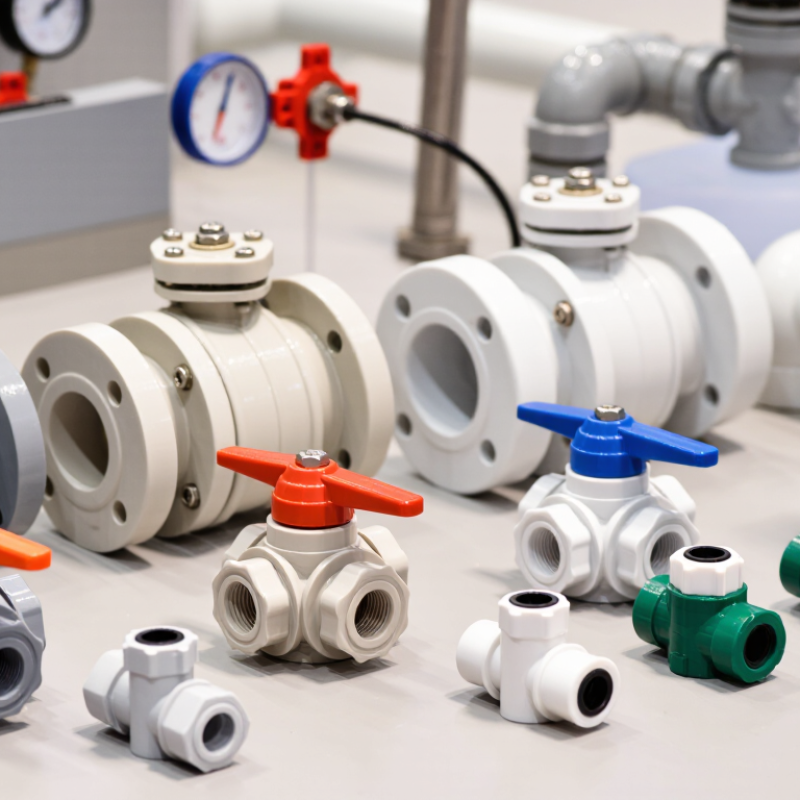
End connections must fit the piping and installation method. Threaded ends are compact, but overtightening can stress plastic threads. Socket connections may use solvent cement, so allow proper assembly and curing time. Flanged ends can simplify maintenance where space permits. For automated systems, size the actuator for valve torque under actual pressure conditions, not just the valve’s nominal size. Consider cycle frequency, power availability, and whether a fail-safe position is needed. Fit matters.
Tips: Confirm pressure and temperature ratings together; ratings can change with heat. Leave room to operate the handle or remove the actuator. One detail is easy to miss: check whether nearby pipe supports prevent strain on the valve. Review the installation plan before ordering.

Cepex is the brand for the fluid handling market belonging to the Fluidra group. One of the leading european manufacturer of valves and fittings in thermoplastic materials.
Dedicated to the swimming pool, irrigation and industrial markets, we distribute our products worldwide with the Fluidra commercial network and presence in 46 countries with 136 sales branches.