How to Choose Multi Pair Instrumentation Cable for Your Needs
FLUID HANDLING EXPERTS

Blog, all our news

How to Choose Multi Pair Instrumentation Cable for Your Needs

Choosing the right Multi Pair Instrumentation Cable begins with the signal, the site, and the distance between them. A cable routed beside a variable-speed drive faces different interference than one installed in a quiet control room. Count the signal pairs, confirm conductor size, and check shielding, insulation, temperature limits, and installation conditions. Small details matter. A drain wire, for example, can simplify shield termination, but only when the grounding plan is clear.

This guide explains how to compare cable construction with real operating needs, rather than choosing by price or pair count alone. It also considers routing, electrical noise, flexibility, and future maintenance. A cable may meet today’s requirements yet prove awkward in a crowded tray or difficult to terminate at a field instrument. That deserves a second look.

A verified quotation from a named Multi Pair Instrumentation Cable industry expert was not provided, so I cannot responsibly invent or attribute one. Instead, the guide focuses on practical selection criteria that engineers can check against project specifications and manufacturer data sheets. The right choice is rarely the most complicated cable. It is the one whose documented performance fits the environment, protects signal integrity, and remains serviceable after installation. Be specific. Verify the details.
How to Choose Multi Pair Instrumentation Cable for Your Needs

What Is Multi-Pair Instrumentation Cable?

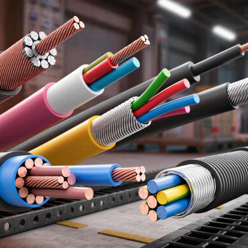
Multi-pair instrumentation cable contains several insulated conductor pairs within one outer jacket. Each pair carries a separate low-level measurement or control signal, such as a temperature sensor reading. Conductors are twisted together to reduce electromagnetic interference. Depending on the installation, pairs may have individual shields, a shared overall shield, or both. The cable is not simply a bundle of wires; its construction helps preserve signal quality in electrically noisy settings.

Pair count, conductor size, insulation, and shielding affect performance and installation. A control cabinet beside a variable-speed motor may need stronger shielding than a short sensor run in a quiet room. IEC 60332-1-2 specifies a 1 kW flame source for its vertical single-cable flame-propagation test. This is a fire-performance measure, not a guarantee of signal accuracy. The distinction matters. No single cable suits every route, and specifying extra shielding without checking grounding can create new problems.

Tips: Check the instrument’s signal type, cable length, noise sources, and environment before choosing. Confirm the cable’s capacitance and temperature rating against the equipment documentation. Keep pairs identified at both ends. A neat installation helps, but I would still verify the wiring and grounding on site.

How to Identify Your Signal and Pair Requirements

How to Choose Multi Pair Instrumentation Cable for Your Needs

How to Identify Your Signal and Pair Requirements

Start by listing every instrument connection, its signal type, and destination. A 4–20 mA loop, low-level thermocouple signal, and digital pulse do not have identical noise needs. Record the source and receiver, expected voltage or current, and whether the circuit is balanced. Note the cable route and approximate length; long runs can increase interference and signal loss. Small details matter.

Count the conductors required for each circuit, then add pairs for future points or spare channels. A two-wire loop usually needs one pair, while some devices need separate pairs for power and data. Check equipment drawings and terminal schedules rather than relying on memory. The first cable schedule is rarely perfect. That is worth admitting. Also identify whether individual pair shielding or an overall shield is specified, especially near motors, variable-speed drives, or other noisy equipment. Follow the instrument and system documentation for grounding and shield termination.

Tips: Make a simple signal list with tag, signal type, pair count, route, and shielding requirement. Keep sensitive analog circuits separate from noisy switching signals when practical. Confirm conductor size against distance, load, and voltage-drop limits. If a signal type or spare count is uncertain, flag it before ordering; guessing can leave too few pairs or an unsuitable cable construction.

Which Cable Construction Fits Your Application?

Start with the signal environment, not the catalog description. In a control cabinet, several low-level sensor signals may share a tray with motor leads. Individually shielded twisted pairs can limit pair-to-pair interference, while an overall foil or braid shield may help manage external electrical noise. These approaches are not interchangeable. A shared shield may suit a relatively quiet route; sensitive analog or communication circuits may need shielding around each pair. Check the equipment documentation and grounding plan before choosing.

Next, match the cable construction to the route. A fixed indoor installation may use a PVC jacket, while outdoor exposure, oil, moisture, or abrasion may call for a more suitable material. Verify the stated resistance rather than guessing from appearance. For trays with sharp edges or possible impact, consider armor, but allow for its added weight and larger bend radius. Measure the actual pathway. Space is easy to underestimate.

Conductor size matters, too. Longer runs and higher current can increase voltage drop and heating, so check the cable ratings against both. Pair count alone is not enough. Review temperature range, capacitance, flexibility, and termination requirements. A cable that fits electrically may still be awkward at a tight gland. I would recheck that detail. Small routing errors can mean costly rework. When requirements conflict, document the trade-offs and ask a qualified engineer to review the specification.

How to Compare Electrical and Environmental Ratings

Compare voltage, conductor resistance, capacitance, and insulation rating against the instrument’s actual signal and installation conditions. NIST’s Copper Wire Tables give copper’s temperature coefficient as about 0.00393 per °C near 20°C. A 30°C conductor rise can therefore increase resistance by roughly 12%, using a simple linear estimate. That may affect loop voltage drop or signal accuracy on long runs. Check the cable data sheet at the expected operating temperature, not only at room temperature. Small details matter.

Environmental ratings deserve equal scrutiny. Confirm the stated temperature range, moisture suitability, oil resistance, sunlight resistance, and permitted installation location. IEC 60332-1-2 defines a vertical flame-propagation test using a 1 kW flame. Passing that test does not mean a cable will maintain circuit function during a fire. Different tests address different hazards. Choose evidence that matches the site.

For a tray near washdown equipment, verify both wet-location suitability and the connector-entry details; a cable rating cannot protect a poorly sealed termination. In a sunlit outdoor run, check for explicit UV resistance rather than assuming a dark jacket is suitable. I would also compare the test method and rating basis across candidate datasheets. Labels can look similar. They are not always equivalent. If the installation conditions are unclear, confirm them before specifying the cable.

How to Choose Multi Pair Instrumentation Cable for Your Needs - How to Compare Electrical and Environmental Ratings

Cable construction Typical electrical ratings and features Environmental and mechanical considerations Best suited to Points to verify before selection
PVC insulation and PVC jacket, overall shield Commonly available with 300 V ratings. PVC conductor temperature ratings are often around 70°C, but depend on the specified cable design. Overall foil or braid shield helps reduce external electrical interference. A general-purpose choice for indoor installations. PVC formulation and cable construction determine resistance to oil, sunlight, moisture, and low temperatures. General process signals and control circuits in relatively mild indoor environments. Check the declared voltage and temperature ratings, shield coverage, minimum bend radius, and whether the jacket is suitable for the site chemicals and ambient conditions.
PVC insulation, individual pair shields, and overall shield Voltage and temperature ratings depend on the complete cable design and are often similar to comparable PVC-insulated constructions. Individual pair shields help limit pair-to-pair interference; the overall shield adds protection from external noise. Environmental suitability is primarily determined by the insulation and outer jacket materials. Shield drain-wire and grounding arrangements should match the installation design. Dense multi-pair runs, low-level analog signals, and installations where crosstalk or electrical noise is a concern. Confirm whether shields are foil, braid, or both; check pair-shield coverage, overall-shield construction, capacitance requirements, and grounding instructions.
PE insulation with a specified outer jacket and shield Polyethylene insulation generally has lower capacitance than PVC insulation in comparable designs, which can benefit some signal circuits. Voltage rating and capacitance are product-specific and must be taken from the cable data sheet. PE insulation resists moisture well, but overall water, UV, oil, and chemical resistance depend on the outer jacket and cable assembly. PE can be less suitable for some fire-performance requirements unless the complete cable is specifically tested and rated. Long signal runs or circuits where cable capacitance is an important design parameter. Compare the specified pair-to-pair and conductor-to-shield capacitance, maximum circuit length, temperature range, jacket material, and required fire tests.
XLPE insulation with a specified jacket and shield Some XLPE-insulated cable designs are rated for conductor temperatures up to 90°C and may be offered with 300 V or 300/500 V ratings. These figures are not universal; use the declared rating for the exact cable. XLPE insulation can support higher operating temperatures than many standard PVC insulation designs. The jacket still determines much of the cable’s resistance to sunlight, oil, moisture, and chemicals. Installations with elevated conductor temperatures or where the specified design requires XLPE insulation. Check the temperature rating of the complete cable, not just its insulation; confirm the outer-jacket limits, voltage rating, and termination temperature limits.
LSZH jacket with insulation and shield selected for the circuit Electrical ratings depend on the insulation and complete cable construction. “LSZH” describes low-smoke, zero-halogen properties; it does not by itself define a voltage rating or guarantee a particular flame-propagation performance. Can be appropriate where smoke and halogen-acid-gas emissions are restricted. Verify test declarations, such as applicable IEC 61034 smoke and IEC 60754 halogen-acid-gas tests, as well as any required flame-propagation test. Public buildings, enclosed spaces, and projects that specify reduced smoke and halogen-acid-gas emissions. Specify the required test methods and acceptance criteria. Also confirm voltage, temperature, UV, water, and chemical ratings separately.
Armoured instrumentation cable Armour does not determine the electrical rating. Voltage, capacitance, conductor temperature, and shielding depend on the underlying cable design. Metallic or other specified armour can provide additional mechanical protection. Armour alone does not make a cable waterproof, corrosion-proof, or suitable for direct burial; those properties require explicit design ratings. Routes exposed to mechanical damage or installations that specifically call for an armoured cable. Check armour material, corrosion protection, bonding and earthing requirements, cable glands, bend radius, and any separate direct-burial or water-resistance rating.

Ratings shown are representative selection guidance, not guaranteed specifications. Actual voltage, temperature, capacitance, fire, and environmental performance vary by cable design and applicable standard. Confirm the exact cable data sheet, installation conditions, and project requirements before purchase.

How to Verify Compatibility with Installation Conditions

Verify the cable against the actual installation conditions, not just the instrument’s nameplate. Confirm the number of pairs, conductor size, insulation rating, and required signal performance. A cable that fits the terminal may still have excessive resistance or capacitance for a long run.

Check the route for heat, moisture, oils, sunlight, and mechanical wear. A cable passing through a warm equipment room may need a different temperature rating from one installed in a cool control cabinet. Measure the available space, too. Tight conduit bends can strain the cable or exceed its minimum bend radius. Small details matter.

Review the cable’s shield construction and grounding instructions when nearby motors or power conductors could create electrical noise. Check whether the installation uses conduit, trays, or direct burial, and select a jacket rated for that exposure. I have seen compatibility checks focus on voltage while overlooking chemical splashes near pumps. That is an easy miss. Compare the cable data sheet with the site conditions, and ask the installer to verify any uncertain ratings before pulling the cable. Even a careful checklist can miss a local hazard.

How to Choose Multi-Pair Instrumentation Cable for Your Needs

Verify Conductor Resistance Against Installation Requirements

Lower conductor resistance can help limit signal-circuit voltage drop over long runs. Values shown are maximum DC resistance at 20°C for class 2 copper conductors, based on IEC 60228. Before selecting a multi-pair cable, check the cable datasheet and confirm that conductor size, circuit length, operating temperature, shielding, capacitance, and installation environment meet your system requirements.

Copyright 2025 Fluidra S.A. | Created by BCM Marketing Agencia Privacy Policy Legal note | Cookie policy |

Technical cookies are strictly necessary for our website to work and you can navigate through it. These types of cookies are those that, for example, allow us to identify you, give you access to certain restricted parts of the page if necessary, or remember different options or services already selected by you, such as your privacy preferences. Therefore, they are activated by default, your authorization not being necessary in this regard. Through the configuration of your browser, you can block or alert the presence of this type of cookies, although such blocking will affect the proper functioning of the different functionalities of our website.


The analysis cookies allow us to study the navigation of the users of our website in general (for example, which sections of the page are the most visited, which services are used most and if they work correctly, etc.). From the statistical information on navigation on our website, we can improve both the operation of the page itself and the different services it offers. Therefore, these cookies do not have an advertising purpose, but only serve to make our website work better, adapting to our users in general. By activating them you will contribute to this continuous improvement. You can enable or disable these cookies by checking the corresponding box, being disabled by default.


Functionality cookies allow us to remember your preferences, to personalize certain characteristics and general options of our website, every time you access it (for example, the language in which the information is presented to you, the sections marked as favorites, your browser type, etc.) Therefore, this type of cookies does not have an advertising purpose, but by activating them you will improve the functionality of the website (for example, adapting to your type of browser) and the customization of it based on your preferences (for example, by presenting the information in the language that you have chosen in previous occasions), which will contribute to the ease, usability and comfort of our page during your navigation. You can enable or disable these cookies by checking the corresponding box, being disabled by default.


Advertising cookies allow us to manage the advertising spaces included in our website based on criteria such as the content shown or the frequency in which the ads are displayed. For example, if you have been shown the same ad several times on our website, and you have not shown a personal interest by clicking on it, it will not appear again. In summary, by activating this type of cookies, the advertising shown on our website will be more useful and diverse, and less repetitive. You can enable or disable these cookies by checking the corresponding box, being disabled by default.


Behavioral advertising cookies allow us to obtain information based on the observation of your browsing habits and behaviors on the web, in order to show you advertising content that best suits your personal tastes and interests. To understand it in a very simple way, we will give you a fictitious example: if your last searches on the web were related to suspense literature, we would show you advertising about suspense books. Therefore, activating this type of cookies, the advertising that we show you on our website will not be generic, but will be oriented to your searches, tastes and interests, therefore adjusting exclusively to you. You can enable or disable these cookies by checking the corresponding box, being disabled by default.
To understand it in a very simple way, we will give you a fictitious example: if your last searches on the web were related to suspense literature, we would show you advertising about suspense books. Therefore, activating this type of cookies, the advertising that we show you on our website will not be generic, but will be oriented to your searches, tastes and interests, therefore adjusting exclusively to you. You can enable or disable these cookies by checking the corresponding box, being disabled by default.

SAVE

We use our own and third-party cookies to ensure the proper functioning of the website and to analyse our services, improve your experience on our website and show you advertisements related to your interests according to profiling based on your browsing habits (e.g. websites visited). You can accept all cookies by clicking "ACCEPT" or set or reject them by clicking here. If you would like to know more about the use of cookies, please see our COOKIE POLICY.


ACCEPT ALL
Reject no essentials