Choosing Abb Power Factor Correction Capacitors requires more than matching a kvar value to a motor rating. Power factor affects transformer loading, cable capacity, voltage stability, and utility charges. The U.S. Department of Energy identifies motor-driven equipment as responsible for a significant share of industrial electricity use, making efficient motor-system design commercially important. However, capacitors do not automatically reduce every form of energy loss.
A reliable selection process begins with measured operating data. Record real power, reactive power, voltage, current, load variation, and harmonic distortion at the main switchboard. A capacitor bank sized from a nameplate alone may perform poorly when production changes. ABB technical guidance and IEC 60831 requirements emphasize suitable voltage ratings, discharge devices, switching conditions, and thermal performance. These details matter inside a hot electrical room, where dust, poor ventilation, and frequent switching can shorten service life.
Harmonics require particular attention. The IEEE 519 standard provides recommended practices for harmonic control, while modern variable-speed drives can create conditions that make ordinary capacitors unsuitable. Detuned reactors or specialized harmonic-rated banks may be necessary. An incorrect capacitor can amplify resonance rather than solve a power-quality problem.
Field assessments often reveal another weakness: maintenance records are incomplete. That makes future decisions less certain. A practical specification should define target power factor, step control, enclosure conditions, protection, discharge time, and monitoring requirements. ABB Power Factor Correction Capacitors can support dependable system performance, but only when selected against measured conditions and verified after installation. The final design should be reviewed by a qualified electrical professional, especially in facilities with generators, drives, or rapidly changing loads.
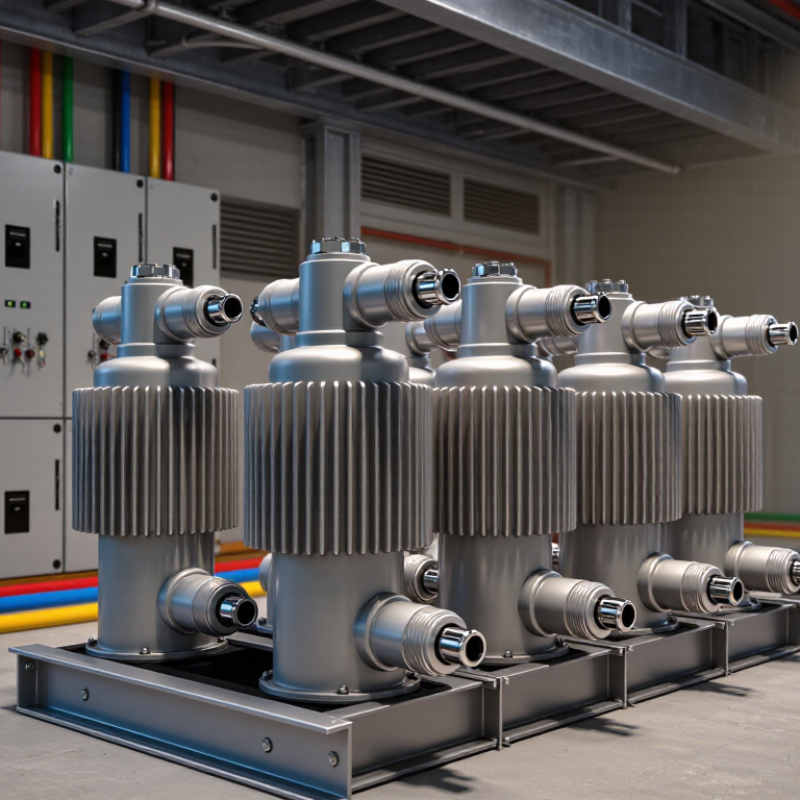
Power factor correction capacitors supply reactive power close to inductive loads. Motors, transformers, and welding equipment often create this demand. The capacitor reduces current flowing through upstream cables and transformers. That can lower losses and release useful system capacity. The basic sizing value is kVAr, not physical size. Measure load current, voltage, operating hours, and power factor before selecting a unit. A clamp meter and power-quality analyzer reveal conditions that nameplate data can miss. Capacitor voltage rating should exceed normal operating voltage. Frequency also matters, because reactance changes with frequency.
Harmonics require careful attention. Capacitors can interact with system inductance and create resonance. In facilities with variable-speed drives, detuned reactors may provide safer correction. Check switching steps, discharge resistors, enclosure temperature, and ventilation. Heat shortens capacitor life, especially inside crowded panels. In practical installations, loose terminals and dust cause more trouble than expected. Torque connections according to the equipment instructions. Leave space for inspection and replacement. A neat calculation can still fail. Real loads change during shifts, and a fixed capacitor bank may overcorrect at light load. Automatic controllers usually respond better, but their settings need verification after commissioning. Record operating voltage, current, temperature, and harmonic distortion during normal production. Then compare those readings with the design assumptions. Perfect data is uncommon. Good engineering includes questioning the gaps.

Choosing power factor correction capacitors starts with understanding the electrical load, not selecting a capacitor from a catalog. Record real power, apparent power, operating voltage, frequency, and power factor during normal production. A single reading can mislead. Measure at different times, especially during motor starting, shift changes, and low-load periods. Short intervals matter.
For a balanced inductive load, the required correction can be estimated with kVAr = kW × (tan φ1 − tan φ2). Here, φ1 represents the existing power factor angle, while φ2 represents the desired angle. Many facilities target a power factor near 0.95 to 0.99. Avoid automatic overcorrection. Leading power factor can create voltage problems and possible utility penalties. Capacitor steps should match the load’s changing demand, rather than remain permanently energized.
Harmonics require closer attention. Variable-speed drives, rectifiers, and switching power supplies can distort current and overheat ordinary capacitors. Review the site’s harmonic measurements before installation. Detuned reactors may reduce resonance risk, but their rating must suit the system voltage and capacitor duty. I have found that incomplete load records often produce oversized banks. That mistake increases switching stress and wastes space. Check enclosure temperature, ventilation, fuses, discharge resistors, and controller response. Recheck the system after installation. The measured result may differ from the calculation.
Choosing power factor correction capacitors starts with measured load behavior, not a catalog table. In field assessments, I record voltage, current, power factor, harmonics, and load changes across a full operating shift. A fixed capacitor may suit a steady motor. It can overcorrect a lightly loaded feeder. Automatic banks fit variable demand better. They switch stages as reactive power changes. Small detail, large consequence. Select the kvar rating from measured demand, not the motor nameplate alone. The voltage rating also needs margin for system conditions and capacitor tolerance.
Configuration depends on the network. Delta connections are common in three-phase systems, while unbalanced loads require closer review. Harmonic-rich sites should use detuned reactors with capacitor stages. Otherwise, resonance can amplify distortion and shorten service life. I once focused too heavily on nominal kvar and underestimated switching frequency. That mistake changed the maintenance plan. Step control, contactor duty, and inrush limiting deserve equal attention. The bank should coordinate with protection settings and discharge devices.
Installation conditions can quietly decide performance. Keep capacitors away from heat, dust, moisture, and corrosive vapors. Check enclosure ventilation and ambient temperature before selecting the assembly. High altitude may reduce cooling effectiveness and insulation margins. Leave room for inspection, torque checks, and safe isolation. Cable size, grounding, and short-circuit withstand must match the installation. Thermal scans and capacitance checks can reveal aging before a sudden trip. Readings may still mislead when loads change quickly, so repeat tests under comparable conditions. Some projects need revision after commissioning. That is normal engineering, not failure.
| Selection Dimension | Recommended Data or Range | How to Select | Installation and Application Notes |
|---|---|---|---|
| Required power factor correction | Calculate from the present power factor and the target power factor, typically 0.95 to 0.99. | Use: Qc = P × [tan(cos⁻¹ PF₁) − tan(cos⁻¹ PF₂)], where Qc is in kVAr and P is active power in kW. | Use measured demand data where possible. Avoid correcting far beyond the practical target because excessive correction can create leading power factor conditions. |
| Capacitor voltage rating | Select a voltage rating equal to or higher than the system line-to-line voltage. Common low-voltage systems include 400 V, 415 V, 440 V, 480 V, and 525 V. | Match the capacitor rating to the actual system voltage, frequency, switching conditions, and expected voltage variation. | A higher voltage-rated capacitor may provide greater tolerance to overvoltage and harmonics, but its delivered kVAr changes with operating voltage. |
| Capacitor reactive power rating | Common step sizes range from approximately 5 kVAr to 100 kVAr per capacitor unit in low-voltage correction systems. | Choose a total bank rating that meets the calculated requirement, then divide it into steps suited to the load profile. | Use smaller steps for rapidly changing or lightly loaded systems and larger steps for stable, continuous loads. |
| Number and size of steps | Typical arrangements include 4, 6, 8, or 12 steps, such as 10 + 10 + 20 + 20 + 40 kVAr. | Select the number of steps according to load variation, minimum demand, and the required control resolution. | A step that is too large can cause overcorrection at low load. Automatic controllers should be configured to prevent unnecessary switching. |
| Fixed or automatic correction | Fixed bank: constant load. Automatic bank: variable load. | Use fixed capacitors for motors or transformers with steady reactive demand. Use stepped automatic banks at main distribution boards with changing loads. | Fixed capacitors require careful sizing to avoid leading power factor when the associated load is disconnected. |
| Harmonic distortion assessment | Review total harmonic distortion, individual harmonic orders, nonlinear load percentage, and resonance risk. | Measure the installation under representative operating conditions before selecting an unprotected capacitor bank. | Variable-speed drives, rectifiers, UPS systems, welding equipment, and switched-mode power supplies can increase harmonic current. |
| Detuned or filtered configuration | Use series reactors with capacitors when harmonic levels or resonance risk is significant. Common detuning factors include approximately 5%, 7%, and 14%, depending on system design. | The reactor-capacitor combination must be designed so its resonant frequency remains below the dominant harmonic and away from troublesome system resonances. | Detuned banks reduce amplification risk but may deliver less effective fundamental-frequency kVAr than an equivalent undetuned bank. |
| Switching method | Electromechanical contactors are common for moderate switching frequency; semiconductor switching is suited to rapid load changes. | Choose the switching method according to the number of operations, transient sensitivity, response time, and load dynamics. | Use capacitor-duty contactors or suitable switching equipment with inrush-current limiting provisions where required. |
| Discharge requirements | Capacitors require discharge devices so the residual voltage falls to a safe level before re-energization or maintenance. | Verify the discharge time specified by the equipment and applicable electrical safety requirements. | Do not rely on manual short-circuiting as a normal discharge method. Isolate, lock out, and verify absence of voltage before work. |
| Ambient temperature | Select equipment for the actual minimum and maximum ambient temperatures; many indoor assemblies are designed around approximately −5 °C to +40 °C, subject to the equipment specification. | Check the capacitor, enclosure, controller, contactor, and reactor temperature limits as a complete assembly. | Provide ventilation or temperature-controlled cooling when heat from capacitors, reactors, cables, or adjacent equipment raises the enclosure temperature. |
| Altitude | Standard equipment ratings often apply up to approximately 1,000 m above sea level, but the applicable product and installation standard must be checked. | For higher elevations, confirm insulation, cooling, and dielectric-clearance derating requirements. | Reduced air density can decrease cooling performance and insulation strength, especially in enclosed switchboards. |
| Enclosure and environmental protection | Select an enclosure protection level suitable for indoor or outdoor location, dust, moisture, corrosive agents, and access conditions. | Consider the required ingress protection, ventilation arrangement, cable entry, and resistance to contamination. | Keep capacitors away from water leaks, conductive dust, corrosive vapors, and direct heat sources. Maintain the manufacturer’s clearances. |
| System frequency | Specify the actual system frequency, commonly 50 Hz or 60 Hz. | Do not interchange frequency ratings without recalculating reactive power, impedance, and resonance characteristics. | Frequency affects capacitor reactance and the tuning point of any series reactor-capacitor combination. |
| Current and overload capability | Account for fundamental capacitor current, harmonic current, switching transients, and permitted short-duration overloads. | Select protective devices and conductors based on the applicable standard and the capacitor assembly’s continuous and transient current requirements. | Harmonic current can cause overheating even when the fundamental-frequency kVAr appears correctly sized. |
| Protection and isolation | Provide short-circuit protection, switching isolation, overcurrent protection, and appropriate upstream disconnecting means. | Coordinate protective devices with capacitor inrush current, fault levels, cable ratings, and the distribution system. | Install visible isolation and clear warning labels. Follow local electrical codes and the equipment manufacturer’s instructions. |
| Power quality and monitoring | Monitor voltage, current, power factor, kVAr, demand, harmonic distortion, temperature, and switching status. | Use a power-quality meter capable of recording conditions during minimum, average, and peak loading. | Periodic measurements help identify failed capacitor elements, blown fuses, contactor wear, overheating, and resonance symptoms. |
Choosing power factor correction capacitors requires more than matching kvar to a motor load. Check the system voltage, frequency, connection method, and operating environment. A capacitor rated too close to the measured voltage may suffer excessive electrical stress during switching or abnormal conditions. I prefer leaving a practical voltage margin, but the exact margin depends on the installation standard and equipment design.
Harmonics deserve close attention. Variable-speed drives, rectifiers, and LED power supplies can distort the current waveform. Capacitors may amplify certain harmonic frequencies, causing overheating, nuisance trips, or premature failure. Measure total harmonic distortion at the installation point instead of relying only on the utility bill. If distortion is significant, consider detuned reactors and verify their tuning against the site’s dominant harmonics. Small details matter.
Temperature is another compatibility test. Review the capacitor’s maximum ambient rating, internal heat path, enclosure ventilation, and expected switching frequency. A cabinet that feels warm during a short inspection may become much hotter in summer. I once treated temperature as a secondary concern, and that was a poor assumption. Also check RMS current, because harmonic current can raise heating even when the capacitor’s kvar appears acceptable. Record measurements under normal and peak loads, then have a qualified engineer confirm the selection before energizing the bank.
Choosing power factor correction capacitors requires more than matching a kvar rating. Plan for protection, maintenance, and future expansion before installation. Field engineers often inspect transformer loading, motor starting currents, ambient temperature, and harmonic-producing equipment. A capacitor bank sized only for today may become inadequate after adding variable-speed drives or electric heating.
Protection should include properly rated fuses, switching devices, discharge resistors, and overtemperature monitoring. IEEE 519-2022 commonly uses 5% voltage total harmonic distortion as a planning limit for systems rated up to 1 kV. Harmonic measurements should guide the choice between standard capacitors and detuned reactors. A clean waveform matters. It protects more than capacitors.
Maintenance planning must be practical. Leave safe working space, label stages clearly, and record monthly current, temperature, and contactor operation. IEC 60831 covers low-voltage self-healing shunt capacitors, but compliance does not replace site inspections. Dust buildup can raise enclosure temperature quickly. That small detail is often missed.
Expansion deserves a spare-capacity allowance. The IEA’s Electricity 2024 report projects global electricity demand growth of about 3.4% annually through 2026. A growing facility may need additional capacitor stages, not a complete replacement. However, oversizing creates another risk: leading power factor during light load. I have seen designs look efficient on paper, then switch too many stages at night. Recheck the load profile before approving the final configuration.
Capacity planning should consider operating conditions, protection margins, maintenance requirements, and future system expansion. The chart compares calculated reactive-power compensation, a 20% expansion allowance, and a practical nominal capacitor-bank selection.
Planning basis: Required correction is calculated as Qc = P × (tan φ₁ − tan φ₂), using a target power factor of 0.95. Final selection should also verify harmonic distortion, switching transients, discharge protection, ventilation, and maintenance access.

Cepex is the brand for the fluid handling market belonging to the Fluidra group. One of the leading european manufacturer of valves and fittings in thermoplastic materials.
Dedicated to the swimming pool, irrigation and industrial markets, we distribute our products worldwide with the Fluidra commercial network and presence in 46 countries with 136 sales branches.