What Is a Bellows Valve and How Do Manufacturers Make It?
FLUID HANDLING EXPERTS

Blog, all our news

What Is a Bellows Valve and How Do Manufacturers Make It?

A bellows valve controls flow while using a flexible metal bellows to help isolate the stem from the process fluid. This design can reduce leakage along the stem, which matters in systems handling hazardous, costly, or highly pure media. It is not a guarantee of zero leakage. Performance depends on materials, operating conditions, workmanship, and correct installation.

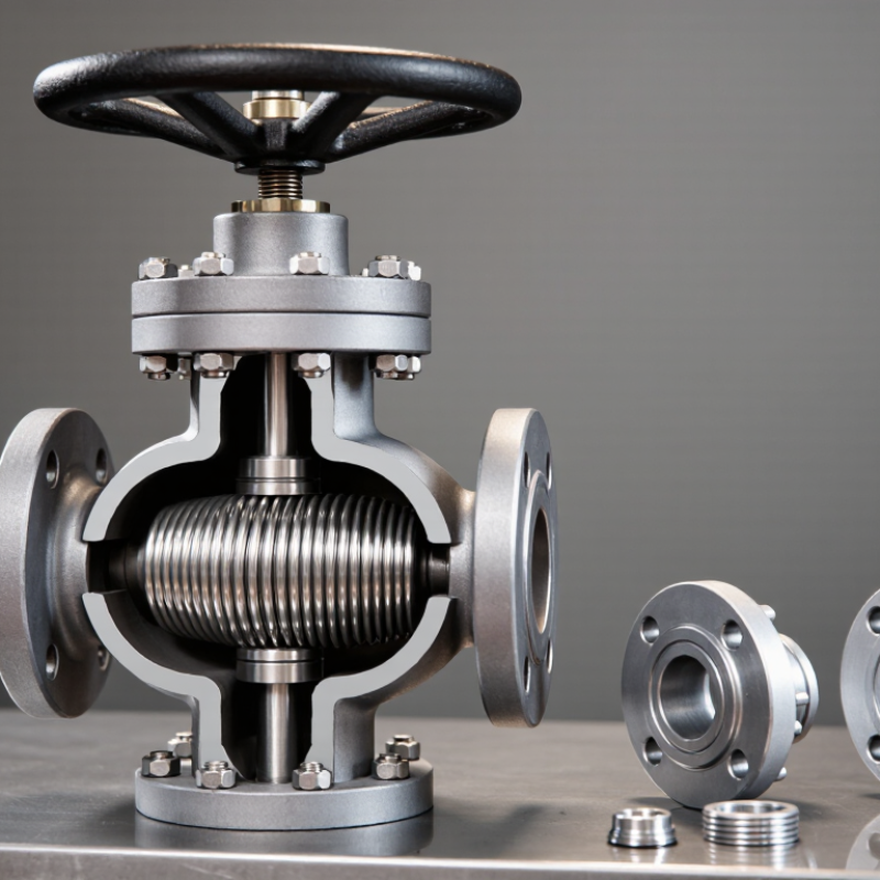
Inside the valve, the bellows compresses and extends as the stem moves. Think of a small metal accordion responding to each turn of the handwheel. Bellows Valves Manufacturers typically begin by selecting compatible materials and defining the pressure, temperature, and cycle requirements. They machine or form the body, shape the bellows, and join it to the stem and valve components. The joining method and inspection criteria vary by design and application.

Small details matter. A tiny weld defect or an unsuitable alloy can shorten service life. Manufacturers may use visual checks, dimensional inspection, pressure testing, and leak testing, with methods selected for the product and its intended use. Buyers should review documented specifications and test results rather than rely on broad claims. A bellows valve may look simple from the outside. Its reliability depends on careful work hidden inside—and that is easy to overlook. Even a well-made valve needs proper selection and maintenance.
What Is a Bellows Valve and How Do Manufacturers Make It?

What a Bellows Valve Does: Metal Bellows Seal the Stem from the Process

What Is a Bellows Valve and How Do Manufacturers Make It?

A bellows valve uses a flexible metal bellows to seal the moving stem from the process fluid. The bellows is joined to the stem and valve body, creating a barrier as the stem rises or lowers. This limits fluid from escaping along the stem, which is especially useful when controlling hazardous, corrosive, or high-purity media. That barrier matters. The bellows flexes with each operation, so its material, wall thickness, and movement range must suit the service conditions. Many designs also include stem packing as a secondary seal if the bellows fails.

Manufacturers typically form thin metal into a series of folds, then weld the bellows to connecting components. The valve body and internal parts are machined to fit, assembled, and checked for leaks. Testing may include pressure checks and repeated operating cycles to reveal weak welds or fatigue. No bellows lasts forever; frequent cycling, vibration, or unsuitable pressure can shorten its service life. Inspection intervals should reflect actual operating conditions, not just a standard schedule.

Tips: Confirm the valve’s pressure, temperature, and cycle limits before installation. Watch for unusual stem movement or leakage near the bonnet. Small details count. Don’t assume a bellows seal removes every maintenance need.

How Manufacturers Select Bellows Alloys and ASME B16.34 Pressure Ratings

A bellows valve separates the process fluid from the stem with a flexible, welded metal element. Choosing its alloy starts with the actual service conditions, not a generic corrosion chart. Manufacturers consider fluid chemistry, operating temperature, pressure changes, and expected movement cycles. A sample of the process fluid can reveal risks that a specification may overlook. Small details matter.

Stainless steel may suit many moderate services, while nickel alloys can offer better resistance to particular corrosive media or higher temperatures. No alloy is universal. A manufacturer should check compatibility data and assess bellows thickness, weld quality, and fatigue life together. A thin bellows may flex easily, but repeated strokes can shorten its service life. That trade-off deserves careful review.

ASME B16.34 establishes pressure-temperature ratings and construction requirements for covered valves. The applicable rating depends on factors such as valve class, body material group, and operating temperature. It is not a standalone rating for the bellows itself. Manufacturers compare the valve design with the relevant code tables, then verify the pressure boundary and test requirements. A class number alone does not tell the whole story. Confirming the specified temperature and material group is essential, and project conditions can still expose assumptions worth revisiting.

How Bellows Are Formed: Hydroformed Tubes or Welded Metal Diaphragms

A bellows valve uses a flexible metal element to separate the process fluid from the moving stem. That barrier can reduce leakage paths and protect the stem from corrosive media. Its reliability depends heavily on how the bellows is formed and joined.

Hydroforming starts with a metal tube sealed at both ends. Internal fluid pressure expands the tube against a shaped die, creating a series of controlled corrugations. The process can produce a continuous bellows without seams along its folds. Wall thickness, material condition, and pressure must be carefully controlled. Too much thinning can shorten fatigue life. Too little forming can leave uneven folds. Small differences matter.

Welded metal diaphragms use a different route. Thin metal discs are stamped or otherwise formed, then joined around their edges to build a flexible stack. The welds must be consistent; a tiny defect may become a leak under repeated movement. This approach allows manufacturers to select diaphragm geometry and stack length for particular valve designs, but it adds critical joining steps. Both methods need inspection and suitable pressure, leak, and movement testing. The best choice is not universal. Service pressure, temperature, fluid compatibility, and expected cycling all matter, and design assumptions should be checked against real operating conditions.

How Bellows Are Formed: Hydroformed Tubes vs. Welded Metal Diaphragms

Idealized profile of one bellows convolution. The vertical axis shows normalized radial displacement; the horizontal axis shows normalized position along one pitch. Profiles are schematic, not production measurements.

Hydroforming expands a tube against a shaped die to create continuous corrugations. Welded diaphragm bellows are assembled by joining formed metal diaphragms, producing a profile represented here with straighter flanks.

How Manufacturers Weld, Assemble, and Test Bellows to ISO 15848-1

A bellows valve’s performance depends on a thin metal barrier and the welds that seal it. Manufacturers form metal diaphragms into convolutions, then weld their edges into a flexible assembly. Weld penetration, alignment, and heat input matter: a tiny pinhole can become a leak after repeated movement. Each bellows is inspected for dimensional consistency and weld defects before it is attached to the valve stem and body. Small details matter.

Assembly must protect the bellows from twisting or compression beyond its design travel. Technicians align the stem, guide, and bonnet, then verify smooth operation and specified stroke. ISO 15848-1:2015 provides a framework for qualifying industrial valves against fugitive emissions, including stem-seal tightness, temperature, and endurance classes. Its endurance categories range from CO1 at 205 mechanical cycles to CO5 at 20,000 cycles. These are qualification test levels, not a guarantee that every service condition is covered.

Testing commonly combines pressure checks with helium leak detection, which can reveal very small leakage paths around welds and sealing interfaces. The test record should identify the valve configuration, test medium, temperature, cycle count, and measured leakage, so results can be traced to the tested design. ISO 15848-1 sets classification and test procedures; manufacturers still need to select conditions that represent the intended service. A clean test result is useful, but it cannot replace careful installation or maintenance.

Final Pressure Checks: API 598 Shell Testing at 1.5× MAWP at 100°F

For a bellows valve, the final shell test checks the pressure-retaining body, not just the flexible metal bellows. API 598 specifies shell-test pressure at 1.5 times the valve’s maximum allowable pressure at 100°F. The pressure basis should match the valve’s rating, with ASME B16.34 providing pressure-temperature rating information for applicable valve materials and classes. Check the governing editions and purchase specification; the exact rating basis matters.

On the test stand, technicians isolate the valve ends, fill the body with test liquid when hydrostatic testing is specified, and raise pressure gradually. A calibrated gauge makes the reading useful. Inspectors look for visible leakage through the body, bonnet joint, or pressure-boundary connections during the required hold. No leaks. API 598 sets minimum shell-test durations by valve size, so a brief glance is not a substitute for the specified hold time. Records should capture test pressure, duration, medium, temperature, and result. That sounds routine, but recording the wrong rating basis can make a precise-looking test misleading.

The shell test does not prove every bellows will survive repeated cycling or thermal movement. Those concerns need appropriate design review and separate qualification evidence. Real test setups also have limits: trapped air, gauge error, or an unclear acceptance record can weaken confidence. It is worth pausing over those details. API 598 and ASME B16.34 are the relevant industry references; their requirements should be checked against the project specification and the valve’s documented rating.

What Is a Bellows Valve and How Do Manufacturers Make It? - Final Pressure Checks: API 598 Shell Testing at 1.5× MAWP at 100°F

Check or Data Dimension Requirement or Example Purpose and Interpretation
Test standard API 598, using the applicable edition and purchase specification Provides valve inspection and pressure-test requirements. The specified edition should be confirmed for each order.
Shell-test pressure basis 1.5 × the valve’s maximum allowable working pressure (MAWP) referenced to 100°F The MAWP must be established for the valve’s materials, pressure class, and design. The test pressure is not determined from nominal pipe size alone.
Illustrative calculation A Assumed MAWP at 100°F: 150 psi; calculated shell-test pressure: 225 psi Example arithmetic only: 150 psi × 1.5 = 225 psi. This is not a pressure rating assigned to a particular valve class.
Illustrative calculation B Assumed MAWP at 100°F: 300 psi; calculated shell-test pressure: 450 psi Example arithmetic only: 300 psi × 1.5 = 450 psi. Use the documented MAWP for the actual valve.
Illustrative calculation C Assumed MAWP at 100°F: 600 psi; calculated shell-test pressure: 900 psi Example arithmetic only: 600 psi × 1.5 = 900 psi. The valve’s allowable test pressure and applicable standard remain controlling.
Minimum shell-test duration by nominal size NPS 2 and smaller: 15 seconds
NPS 2½–6: 60 seconds
NPS 8–12: 120 seconds
NPS 14 and larger: 300 seconds
These are API 598 minimum shell-test durations by size range. Apply the relevant standard edition and any stricter contractual requirement.
Test medium and setup Use a suitable liquid or gas test medium and the valve configuration permitted by the applicable procedure. The medium, temperature, isolation, and pressure application method should be selected and controlled in accordance with the standard and the approved test procedure.
Shell-test acceptance No visible leakage through pressure-retaining shell boundaries during the required test period Inspect the body, bonnet, and pressure-retaining joints included in the test arrangement. Acceptance criteria should follow the applicable API 598 requirements.
Bellows-specific verification Perform any specified bellows leak or integrity test separately when required by the design, procedure, or purchase specification. An API 598 shell test checks the pressure-retaining shell under its prescribed conditions; it does not by itself establish every bellows or stem-seal performance requirement.
Test record Record valve identification, size, MAWP basis, calculated test pressure, test medium, duration, result, and test date. Traceable records help demonstrate that the final pressure check was performed against the correct valve-specific requirements.

Note: The pressure figures above are illustrative calculations, not published ratings for a specific valve. Confirm the valve’s documented MAWP, applicable API 598 edition, and project requirements before testing.

Copyright 2025 Fluidra S.A. | Created by BCM Marketing Agencia Privacy Policy Legal note | Cookie policy |

Technical cookies are strictly necessary for our website to work and you can navigate through it. These types of cookies are those that, for example, allow us to identify you, give you access to certain restricted parts of the page if necessary, or remember different options or services already selected by you, such as your privacy preferences. Therefore, they are activated by default, your authorization not being necessary in this regard. Through the configuration of your browser, you can block or alert the presence of this type of cookies, although such blocking will affect the proper functioning of the different functionalities of our website.


The analysis cookies allow us to study the navigation of the users of our website in general (for example, which sections of the page are the most visited, which services are used most and if they work correctly, etc.). From the statistical information on navigation on our website, we can improve both the operation of the page itself and the different services it offers. Therefore, these cookies do not have an advertising purpose, but only serve to make our website work better, adapting to our users in general. By activating them you will contribute to this continuous improvement. You can enable or disable these cookies by checking the corresponding box, being disabled by default.


Functionality cookies allow us to remember your preferences, to personalize certain characteristics and general options of our website, every time you access it (for example, the language in which the information is presented to you, the sections marked as favorites, your browser type, etc.) Therefore, this type of cookies does not have an advertising purpose, but by activating them you will improve the functionality of the website (for example, adapting to your type of browser) and the customization of it based on your preferences (for example, by presenting the information in the language that you have chosen in previous occasions), which will contribute to the ease, usability and comfort of our page during your navigation. You can enable or disable these cookies by checking the corresponding box, being disabled by default.


Advertising cookies allow us to manage the advertising spaces included in our website based on criteria such as the content shown or the frequency in which the ads are displayed. For example, if you have been shown the same ad several times on our website, and you have not shown a personal interest by clicking on it, it will not appear again. In summary, by activating this type of cookies, the advertising shown on our website will be more useful and diverse, and less repetitive. You can enable or disable these cookies by checking the corresponding box, being disabled by default.


Behavioral advertising cookies allow us to obtain information based on the observation of your browsing habits and behaviors on the web, in order to show you advertising content that best suits your personal tastes and interests. To understand it in a very simple way, we will give you a fictitious example: if your last searches on the web were related to suspense literature, we would show you advertising about suspense books. Therefore, activating this type of cookies, the advertising that we show you on our website will not be generic, but will be oriented to your searches, tastes and interests, therefore adjusting exclusively to you. You can enable or disable these cookies by checking the corresponding box, being disabled by default.
To understand it in a very simple way, we will give you a fictitious example: if your last searches on the web were related to suspense literature, we would show you advertising about suspense books. Therefore, activating this type of cookies, the advertising that we show you on our website will not be generic, but will be oriented to your searches, tastes and interests, therefore adjusting exclusively to you. You can enable or disable these cookies by checking the corresponding box, being disabled by default.

SAVE

We use our own and third-party cookies to ensure the proper functioning of the website and to analyse our services, improve your experience on our website and show you advertisements related to your interests according to profiling based on your browsing habits (e.g. websites visited). You can accept all cookies by clicking "ACCEPT" or set or reject them by clicking here. If you would like to know more about the use of cookies, please see our COOKIE POLICY.


ACCEPT ALL
Reject no essentials